Premium Only Content

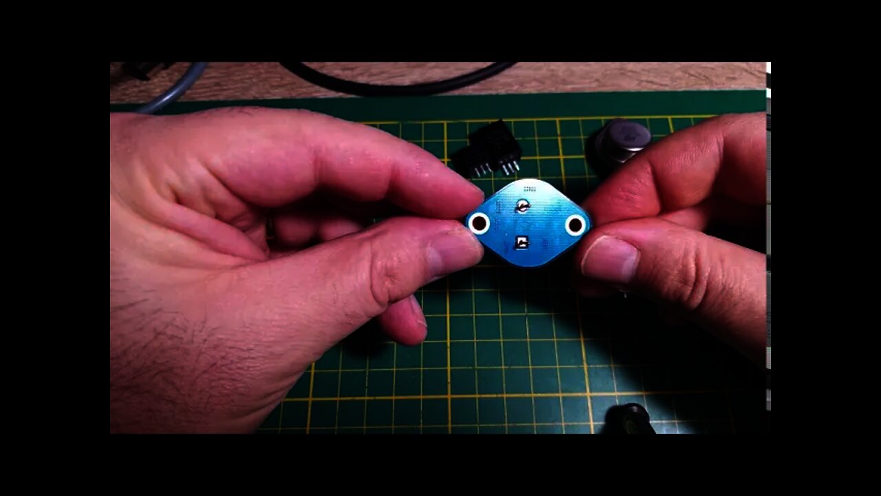
Build your own switch mode voltage regulator for your Commodore VIC 20. Replace the obsolete LM323K.
To reduce the current in my Commodore VIC 20, I decided to change the LM323K linar regulator with an switchmode voltage regulator. I start a small project and create the schematic in KiCAD and order the PCB from JLCPCB. All the components are in surfacemount and it was easy to essably them by hand in my lab.
The switch-mode regulators are open hardware now! You can dowload the gerber files from Github:
https://github.com/DigitalArtDeco/SwitchModePSUinTO3
This is a switching voltage regulator for replace the obsolete LM323K. It is a synchronous buck (step-down) converter. It provides an output voltage of 5 V. The input voltage can be 4,5 to 24 Volts with a continuous current of 3 amps! At room temperature, it does not need a heatsink! The switching voltage regulator operates with a frequency of 500kHz. This device has the same shape as the original TO-3 package. The TO-3 package was used in old devices like game consoles, computers from the 1980 and pinball machines. Therefore you can use this switching voltage regulator to replace your old linear regulators and prevent from damage your old machines. Extremely low ripple and noise! The Pins and the surface of the device are gold plated. The design of the regulator was done with precise calculation and test in the lab. The pcb traces was done to meet the radiation and emission regulations!
Features:
Output Ripple (20MHz bandwidth) with 12V input and with a current of 0,5A: 15mV p-p !!
Wide input range from 4,5 - 24 Volts DC Fixed output voltage of 5 Volts DC
Efficiency up to 96%!
Voltage drop from no load to full load: less than 0,95 %
Low Profile
Short-circuit protection and thermal shutdown
Shielded Power Inductor
Music: By masterdrwho
-
 7:31
7:31
Retro with Pedro
4 years agoFix the "Brick of death". Commodore 64 Powersupply update. Recap and replace the voltage regulator.
39 -
 12:04
12:04
Endless Money Pits
3 years agoAdjustable External Voltage Regulator Installation
24 -
 3:54
3:54
getajobintech
3 years agoBuild your own I.T. Training Lab
34 -
 10:27
10:27
Rural Life with Max Irish
3 years agoBuild Your Own Archery Target!
97 -
 13:44
13:44
retromoderngaming
3 years ago $0.01 earnedSwitch Attract Mode
55 -
 0:48
0:48
carcomputers
3 years ago $0.02 earned93 dodge pcm voltage regulator issue
99 -
 1:02
1:02
How To Do Yourself Channel
3 years ago $0.02 earnedHow To Replace Battery In A VE Holden Commodore Key
80 -
 16:23
16:23
Politics, Permaculture and Food
3 years ago $0.01 earnedBuild Your Own Hard Dodger
73 -
 1:26:22
The Quartering
14 hours agoTrump In Dubai, Democrats BUSTED Funding Attacks On Tesla, DOGE Covid BOMBSHELL & Bernie Sanders
94.2K83 -
 1:39:57
Russell Brand
16 hours agoTYRANNY In Europe as Romanian Right-Wing Presidential Frontrunner BANNED from Elections – SF550
163K49