Process and Instrumentation Diagrams
### **Process and Instrumentation Diagrams (P&IDs): An Overview**
A **Process and Instrumentation Diagram (P&ID)** is a detailed schematic representation of a process system, showing the relationships between equipment, pipelines, instrumentation, and control devices. It is a critical tool in engineering, design, and operations for industries like chemical, oil and gas, pharmaceuticals, and power generation.
---
### **Purpose of P&IDs**
1. **System Design**:
- Provides engineers with a comprehensive visual of the process flow.
- Helps in designing and troubleshooting the system.
2. **Operation and Maintenance**:
- Guides operators in understanding system functionality.
- Identifies equipment and instrumentation locations for maintenance.
3. **Safety and Compliance**:
- Identifies potential hazards and ensures proper safety measures.
- Ensures compliance with regulatory standards.
4. **Project Management**:
- Acts as a reference during construction and commissioning phases.
---
### **Key Components of a P&ID**
A P&ID includes a combination of symbols, labels, and lines to represent the following components:
#### **1. Process Equipment**
- **Pumps**: Centrifugal, positive displacement.
- **Compressors**: Reciprocating, screw, or centrifugal.
- **Heat Exchangers**: Shell and tube, plate, or air-cooled.
- **Reactors**: Chemical reactors or furnaces.
- **Tanks and Vessels**: Storage tanks, process vessels.
#### **2. Pipelines**
- Represented as lines with labels indicating pipe size, material, and flow direction.
- May include markers for insulation or heating.
#### **3. Instrumentation**
- **Sensors**: Temperature, pressure, flow, level, etc.
- **Transmitters**: Devices that send signals to a control system.
- **Controllers**: PID controllers for automated regulation.
- **Valves**: Control, safety relief, check, etc.
#### **4. Control Systems**
- **DCS (Distributed Control Systems)**: Centralized control panels.
- **SCADA (Supervisory Control and Data Acquisition)**: Remote monitoring systems.
#### **5. Utility Systems**
- Includes cooling water, steam, compressed air, and fuel systems.
---
### **Symbols and Notations**
P&IDs rely on standard symbols defined by international standards such as:
- **ISA 5.1 (Instrumentation Symbols and Identification)**.
- **ISO 10628 (Diagrams for Chemical and Petrochemical Industry)**.
#### Common Symbols:
- **Equipment**: Rectangles for tanks, circles for pumps, etc.
- **Instruments**: Circles with tags (e.g., PT for Pressure Transmitter).
- **Valves**: Specific shapes for control, check, and safety valves.
- **Lines**:
- Solid Line: Process flow.
- Dashed Line: Instrument signals.
- Double Line: Major process streams.
---
### **P&ID Example: Key Representation**
**Scenario**: A water pump system with flow and pressure monitoring.
1. **Pump (P)**: Represented by a circle with the tag "P-101."
2. **Piping**: Solid line indicating the flow from the pump to a storage tank.
3. **Flow Sensor (FT)**: Circle with "FT-101" indicating flow measurement.
4. **Pressure Transmitter (PT)**: Circle with "PT-101" indicating pressure monitoring.
5. **Control Valve (CV)**: Symbol indicating an automated valve for regulating flow.
---
### **How to Read a P&ID**
1. **Start with the Legend**: Understand the symbols and notations specific to the P&ID.
2. **Follow the Flow**: Trace pipelines from the source (e.g., pump) to the destination (e.g., tank).
3. **Identify Equipment**: Locate pumps, valves, and instruments using the tags provided.
4. **Analyze Control Systems**: Identify how sensors and controllers interact with equipment.
---
### **Applications of P&IDs**
1. **Process Design**:
- Used during the design phase to outline system operations.
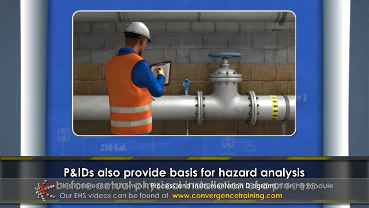
2. **Hazard Analysis**:
- Identifies critical areas for safety and environmental risks.
3. **Maintenance**:
- Helps technicians locate components for repairs or inspections.
4. **Training**:
- Used to train operators on process understanding and control.
---
### **Tips for Creating or Using P&IDs**
1. **Use Standard Symbols**: Ensure symbols conform to industry standards.
2. **Keep It Updated**: Reflect changes in the process or equipment.
3. **Label Clearly**: Avoid ambiguous or missing tags.
4. **Simplify Where Possible**: Avoid unnecessary details that clutter the diagram.
5. **Validate Accuracy**: Verify with operators and engineers during design or updates.
---
If you need help with interpreting or designing a specific P&ID, let me know! I can guide you further. 😊
-
 25:48
25:48
Adam Does Movies
1 day ago $3.39 earnedTop 10 Reasons Why Emilia Pérez Is Complete TRASH!
55.8K7 -
 26:56
26:56
MYLUNCHBREAK CHANNEL PAGE
1 day agoUnder The Necropolis - Pt 6
202K51 -
 6:03
6:03
Tactical Advisor
1 day agoEverything New From Panzer Arms 2025
34.9K1 -
 1:15:59
CarlCrusher
22 hours agoUFOs & Paranormal Phenomena are Not Imaginary | Dr Jim Segala MUPAS Phase 2
39K2 -
 12:44
12:44
BlackDiamondGunsandGear
17 hours agoRadian Ramjet & Afterburner / Worth it? / Which Shoots Flatter?
51.6K4 -
 49:10
49:10
CharLee Simons Presents Do Not Talk
10 days agoDO NOT TALK with GIL MAZA & SAM ANTHONY (Mass Deportation Results)
33K -
 8:07
8:07
Tundra Tactical
23 hours ago $4.75 earnedHiPoint Embraces The MEME Yet Again.
63K8 -
 36:00
36:00
hickok45
10 hours agoSunday Shoot-a-Round # 267
18.4K14 -
 38:57
38:57
PMG
20 hours ago $0.88 earnedHannah Faulkner and Brandon Tatum | BREAKING THE CHAINS: Exposing the Left’s Manipulation
12.1K -
 11:46
11:46
GBGunsRumble
1 day agoSomething Unusual
9.09K3