Premium Only Content
Motor Control Circuits and Functions
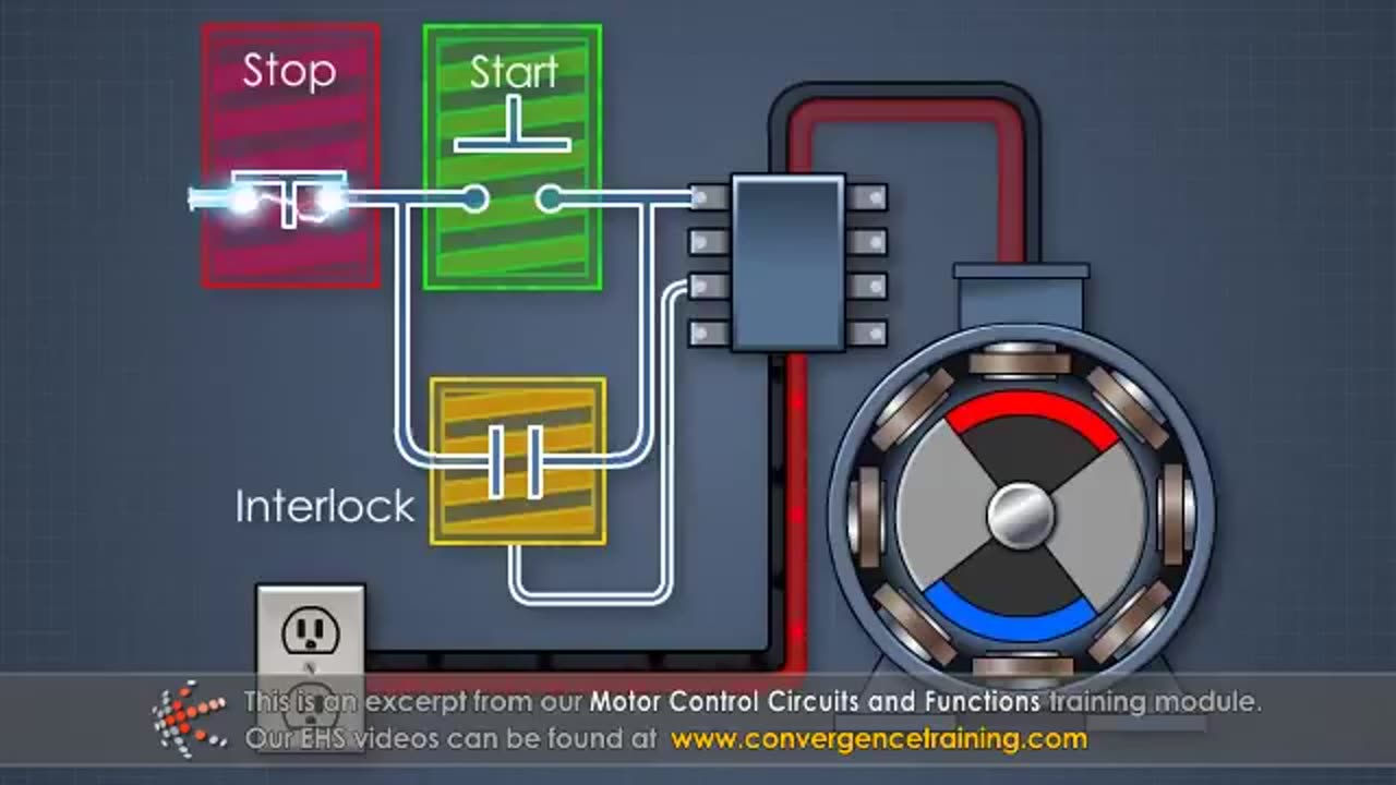
A **motor control circuit** is designed to start, stop, and control the speed or direction of an electric motor. These circuits are widely used in industrial automation, robotics, and machinery. Here's a detailed breakdown:
---
### **Key Components of Motor Control Circuits**
1. **Power Supply**: Provides the necessary electrical energy for the motor.
2. **Motor**: Converts electrical energy into mechanical motion.
3. **Switching Devices**:
- **Contactors**: Electromagnetic switches used to start/stop motors by connecting/disconnecting power.
- **Relays**: Smaller switches that control circuits based on input signals.
4. **Protection Devices**:
- **Overload Relays**: Protect motors from overheating or excessive current.
- **Fuses/Circuit Breakers**: Prevent damage caused by short circuits or overcurrent.
5. **Control Devices**:
- **Push Buttons**: Manual start/stop controls.
- **Selector Switches**: Allow selection between modes (e.g., forward/reverse).
- **Sensors**: Detect motor conditions like speed, position, or load.
6. **Control Circuit**: The low-voltage part of the system that handles commands and logic.
7. **Wiring**: Connects components within the circuit.
---
### **Functions of Motor Control Circuits**
1. **Starting the Motor**:
- **Direct On-Line (DOL) Starter**: Simple circuit for starting small motors directly at full voltage.
- **Star-Delta Starter**: Reduces starting current for large motors by initially connecting in a "star" configuration and later switching to "delta."
- **Soft Starters**: Gradually increase voltage to avoid sudden inrush current.
2. **Stopping the Motor**:
- Controlled using stop buttons or safety switches.
- Some circuits include braking mechanisms (e.g., dynamic or regenerative braking).
3. **Speed Control**:
- **Variable Frequency Drives (VFDs)**: Adjust motor speed by varying input frequency and voltage.
- **Resistive Control**: Uses resistors to limit power (common in DC motors).
4. **Direction Control**:
- Use **reversing contactors** to change motor direction by swapping the connections of motor phases.
5. **Protection**:
- Detects faults like overloads, phase loss, or voltage imbalances and disconnects the motor to prevent damage.
6. **Automation**:
- Control motor operation based on external signals (e.g., sensors or timers) in automated systems.
---
### **Types of Motor Control Circuits**
1. **Manual Control**:
- Operated directly by a person using switches or push buttons.
2. **Automatic Control**:
- Operates without human intervention based on programmed logic (e.g., PLC or timers).
3. **Remote Control**:
- Operates motors from a distance using wired or wireless controls.
4. **Programmable Control**:
- Uses advanced controllers like PLCs (Programmable Logic Controllers) or HMIs (Human-Machine Interfaces) for complex operations.
---
### **Examples of Motor Control Circuits**
1. **DOL Starter Circuit**:
- Simplest motor starter circuit with a contactor, overload relay, and push buttons.
2. **Reversing Starter Circuit**:
- Includes two contactors and an interlocking mechanism to change motor direction.
3. **VFD Circuit**:
- Incorporates a VFD for speed control and smooth motor operation.
---
### **Applications of Motor Control Circuits**
- **Industrial Automation**: Conveyor belts, robotics, assembly lines.
- **HVAC Systems**: Fans, pumps, and compressors.
- **Transportation**: Electric trains, elevators, and escalators.
- **Home Appliances**: Washing machines, mixers, and air conditioners.
---
Motor control circuits are foundational in any system requiring electric motors. Let me know if you’d like to explore wiring diagrams, specific configurations, or troubleshooting tips! 😊
-
 1:25:53
Kim Iversen
3 days agoStriking Back: Taking on the ADL’s Anti-Free Speech Agenda
74K34 -
 49:35
49:35
Donald Trump Jr.
12 hours agoA New Golden Age: Countdown to Inauguration Day | TRIGGERED Ep.202
154K170 -
 1:14:34
Michael Franzese
11 hours agoWhat's Behind Biden's Shocking Death Row Pardons?
68.7K43 -
 9:49
9:49
Tundra Tactical
9 hours ago $15.74 earnedThe Best Tundra Clips from 2024 Part 1.
88.6K7 -
 1:05:19
Sarah Westall
9 hours agoDying to Be Thin: Ozempic & Obesity, Shedding Massive Weight Safely Using GLP-1 Receptors, Dr. Kazer
78.5K20 -
 54:38
54:38
LFA TV
1 day agoThe Resistance Is Gone | Trumpet Daily 12.26.24 7PM EST
57.3K9 -
 58:14
58:14
theDaily302
18 hours agoThe Daily 302- Tim Ballard
57.1K9 -
 13:22
13:22
Stephen Gardner
12 hours ago🔥You'll NEVER Believe what Trump wants NOW!!
106K273 -
 54:56
54:56
Digital Social Hour
1 day ago $10.83 earnedDOGE, Deep State, Drones & Charlie Kirk | Donald Trump Jr.
59.2K5 -
 DVR
DVR
The Trish Regan Show
13 hours agoTrump‘s FCC Targets Disney CEO Bob Iger Over ABC News Alleged Misconduct
64.2K38