Premium Only Content

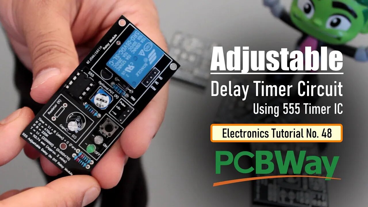
555 Adjustable Delay On Off Timer Circuit
PCBway: only $5 for 10 pcbs from https://www.pcbway.com/?from=CZcouple
The 555 timer IC is an integrated circuit (IC) that is used in a variety of timer, delay, pulse generator and oscillator circuits.
In this tutorial, I am going to show you guys how to make an "Adjustable Delay Timer Circuit" using the 555 timer IC. This circuit can automatically turn on/off any circuit after a fixed duration. This timer circuit is useful when you need to power On/Off any AC Appliances after a pre-defined duration. For example, you can use this circuit to automatically turn off a mobile charger after a certain period of time to avoid over charging, or you can turn on/off a light bulb after a certain period.
The time delay of this circuit can be adjusted by using various combinations of resistors and capacitors.
Watch this video for detailed step by step instructions on how to build this circuit and to know how this circuit works.
Thanks
------
Thanks again for checking my post. I hope it helps you.
If you want to support me subscribe to my YouTube Channel: https://www.youtube.com/user/tarantula3
PCBWay 6th Project Design Contest: https://www.pcbway.com/activity/6th-project-design-contest.html
Video: https://youtu.be/AB8XjBGvlPY
Full Blog Post:
DIY - Relay Module: https://youtu.be/3n69b4sdDjk
Schema:
Circuit:
Gerber Files:
Support My Work
BTC: 1Hrr83W2zu2hmDcmYqZMhgPQ71oLj5b7v5
LTC: LPh69qxUqaHKYuFPJVJsNQjpBHWK7hZ9TZ
DOGE: DEU2Wz3TK95119HMNZv2kpU7PkWbGNs9K3
ETH: 0xD64fb51C74E0206cB6702aB922C765c68B97dCD4
BAT: 0x9D9E77cA360b53cD89cc01dC37A5314C0113FFc3
LBC: bZ8ANEJFsd2MNFfpoxBhtFNPboh7PmD7M2
COS: bnb136ns6lfw4zs5hg4n85vdthaad7hq5m4gtkgf23 Memo: 572187879
BNB: 0xD64fb51C74E0206cB6702aB922C765c68B97dCD4
MATIC: 0xD64fb51C74E0206cB6702aB922C765c68B97dCD4
Thanks, ca gain in my next tutorial.
-
 LIVE
LIVE
Vigilant News Network
3 hours agoHillary CRUSHED by Hegseth After She Suggests His KREMLIN Ties | The Daily Dose
736 watching -
 2:05:00
The White House
4 hours agoPresident Trump Makes an Investment Announcement
15.4K7 -
 1:52:30
The Quartering
3 hours agoWW3 Is Imminent, Trump Must Leave NATO, Zelensky SCAMS Europe For Boots On Th Ground!
63.7K37 -
 1:46:28
Tucker Carlson
3 hours agoErnst Roets: Attacks on Whites in South Africa, Attempts to Hide It, and Trump’s Plan to End It
96.3K61 -
 42:26
42:26
Stephen Gardner
1 hour ago🔥You WON'T BELIEVE What Adam Schiff Said About Trump and Americans!!
13.3K21 -
 1:13:34
Russell Brand
16 hours agoThey Lied to Us – The Vaccine, Big Pharma & Global Corruption with Dr. Aseem Malhotra – SF546
180K106 -
 42:08
42:08
CryptoWendyO
2 hours ago $0.73 earnedTRUMP PUMPS CRYPTO MASSIVE ANNOUNCEMENT COMING
13.9K2 -
 1:57:58
The Charlie Kirk Show
3 hours agoZelensky’s Setup? + Border Recovery | Sen. Mullin, Hemingway, Bensman | 3.3.25
112K43 -
 55:30
55:30
The Dan Bongino Show
6 hours agoThe Explosive White House Meeting That Changed Everything (Ep. 2434) - 03/03/2025
826K1.68K -
 2:10:15
Benny Johnson
4 hours ago🚨 AOC Going to JAIL For Leaking ICE Raid!? Trump to END Military Aid to Ukraine After WH Boss Move
151K196