Displacement Current Transducer Circuit
This circuit presents an innovative approach to energy capture and storage using the single-wire input from a 110V AC mains source. By employing a non-return path for the mains electricity, the system exploits the Heaviside energy flow component and enables the collection of potential without conventional current flow.
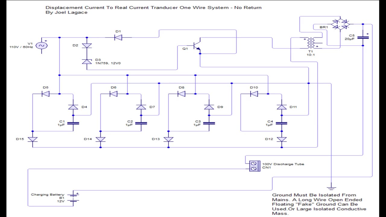
At the core of the system is a single-wire connection that incorporates two diodes in series to establish a differentiation between the positive and negative potentials. These diodes allow the system to rectify the AC input, capturing around 20 volts of pure potential energy.
A 12V Zener diode is configured in reverse breakdown mode to act as a precise trigger mechanism. Once the potential reaches approximately 20V, in line with the peak of the AC cycle, the Zener diode permits a short spike to pass through. This transient spike is crucial as it activates an NPN transistor, which then pulses a bank of microfarad capacitors. These capacitors are individually charged via the live mains, each paired with its own set of diodes to prevent inter-capacitor discharge.
The system's grounding is executed through an isolated ground separate from the mains network, fostering the creation of displacement current. This type of current is typically overlooked but is inherently present in all electrical systems. By connecting to an isolated ground, the system does not complete the loop in the traditional electrical sense, thereby avoiding the generation of counter-electromotive force (CEMF).
The transistor is self-oscillated by the 60Hz mains frequency and directs the bank of capacitors to discharge in synchrony into a low-voltage, 60Hz primary transformer side. The resulting high-voltage spike from the transformer is then rectified through a standard full-bridge rectifier that charges a 20µF capacitor. This capacitor is connected to a 12V battery, intended for charging.
Additionally, the circuit integrates a 100V gas discharge tube in series with the negative pole, which ensures that the 20µF capacitor discharges at a high voltage into the 12V battery. This action is visually confirmed by the gas discharge tube flashing, indicative of the voltage conversion and the transfer of energy into the battery. The process converts the captured displacement current back into real, usable current and stores it in the battery without imposing any input current stress on the closed-loop AC mains system.
This setup, by theory, provides a novel method to convert and store unused potential energy from the mains into a battery for later use, highlighting a unique application of Maxwellian principles and the Heaviside component in practical energy systems.
Forum http://typeright.social/forum
Please Help Support My Research https://youtu.be/pYXETBB40j0
Archive.org Backup https://archive.org/details/displacement-current-transducer-circuit
-
 17:59
17:59
Joel Lagace
7 months ago $0.13 earnedModern Moray Generator
2364 -
 2:11:11
TheSaltyCracker
4 hours agoTrump Fires Everyone ReeEEeE Stream 01-31-25
115K242 -
 1:15:45
Roseanne Barr
6 hours ago $18.45 earnedJFK case solved!? with Shane Stevens | The Roseanne Barr Podcast #85
60.6K43 -
 10:36:04
Dr Disrespect
12 hours ago🔴LIVE - DR DISRESPECT - PUBG - WHAT WINNING LOOKS LIKE
225K36 -
 4:41:07
Nerdrotic
9 hours ago $28.17 earnedCap 4 and Emelia Perez BACKLASH! Acolyte is Still CANCELED! Hollywood STFU | Friday Night Tights 339
169K27 -
 57:41
57:41
The StoneZONE with Roger Stone
5 hours agoWhy Are They So Afraid of Tulsi Gabbard? | The StoneZONE w/ Roger Stone
34K7 -
 LIVE
LIVE
I_Came_With_Fire_Podcast
10 hours ago🔥🔥Suing CHINA, Hillary AIDED RUSSIA, and DEI REMOVED from Military🔥🔥
1,513 watching -
 LIVE
LIVE
SoniCentric
11 hours agoCozy Up With SNOWY Lakeside Cabin Jazz Vibes
118 watching -
 1:36:16
PMG
1 day ago $0.27 earnedSPECIAL: JUSTICE FOR JEREMY - NOW!
12.7K3 -
 1:01:01
TheTapeLibrary
13 hours ago $2.09 earnedThe Horrifying True Story of Summerwind Mansion
26.3K4