Flyback Generator Myke Does John Bedini modified Updated
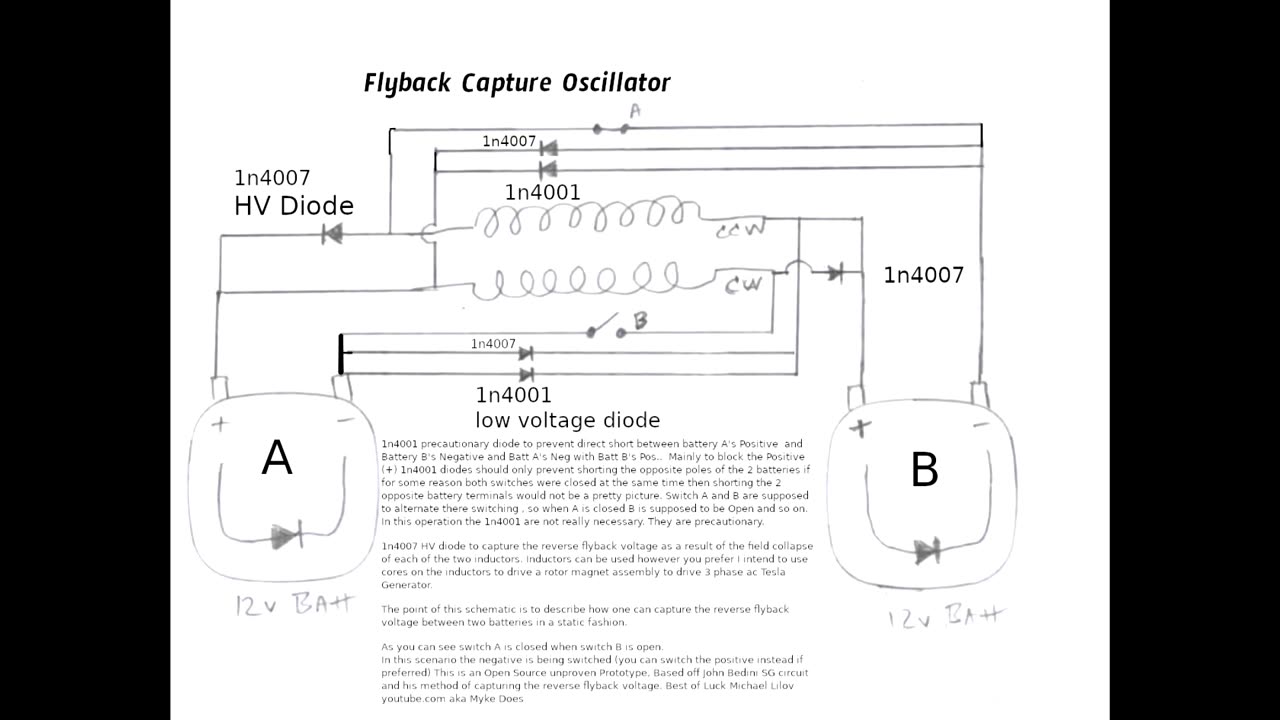
This is a reverse flyback capture circuit designed to capture the flyback between two inductors and two batteries . The point of this circuit is to show how you can capture the flyback avoiding the need to swap the battery positions as done with the single inductor Bedini SG circuit. You could call this a dual inductor Bedini circuit . The addition of the second inductor makes it possible to bounce the flyback between the two batteries using this circuit design . This is open source un proven un built prototype . And open for debate and experiment as to if the 1n4001 blocking diodes are necessary. Have Fun :) (added HV Diode 1n4007 to capture neg flyback voltage ) This circuit main focus is to capture the flyback in alternation between the 2 inductors and the 2 batteries . The Inductor EMF fields can be used how one pleases . (Drive ROTOR Etc or generate AC)
Red indicates forward battery voltage (Source energy is Battery)
Blue indicates reverse flyback voltage (Source Energy is the Reverse Flyback )
This circuit has been updated . See 4 transistor circuit in library . This circuit acts like efficient motor driver much like the Atoms motor captures the flyback into alternate drive inductors this circuit does the same essentially when one inductor is pulsed forward the flyback reverse pulses the other coil virtually simultaneously, if you want the flyback to instead fall into alternate battery as opposed to alternate drive coil see 4 transistor circuit in library
-
 18:38
18:38
The Lou Holtz Show
18 hours agoLou Holtz: "Trump Stands for America—And He Means It!" | Ukraine, Pete Rose & Common Sense 🇺🇸
12.9K3 -
 3:54
3:54
Randi Hipper
18 hours ago$100,000 BITCOIN COMING! HERE'S WHY
2.93K2 -
 9:34
9:34
ariellescarcella
11 hours ago"Born This Way Is A Lie" : Religious Debate
3.51K -
 6:05:13
Akademiks
15 hours agoDay 1/30. Drake Drops lawsuit vs iHeartMedia? Offset and Cardi Calls it Quits. 50 v Jim Jones?
152K13 -
 2:55:11
TimcastIRL
12 hours agoDemocrat TANTRUM At Trump Speech BACKFIRES, Trump Polls UP, Dems UNDER FIRE w/67Kevin | Timcast IRL
223K78 -
 1:25:23
Kim Iversen
14 hours agoFrom Doctor to Political Prisoner: Dr. Simone Gold on COVID Lies, January 6th, and Medical Tyranny
128K79 -
 2:09:28
Melonie Mac
16 hours agoGo Boom Live Ep 39!
83K12 -
 1:04:36
Man in America
17 hours ago🚨 BREAKING: Dr. Robert Young JAILED! Medical Tyrants Will Do ANYTHING to Silence Truth
101K28 -
 3:01:44
I_Came_With_Fire_Podcast
15 hours agoPanama CANAL BlackROCKED | Left of PODCASTING | Ukraine AID GONE
55K7 -
 45:56
45:56
Glenn Greenwald
15 hours agoLee Fang Reacts to Trump's Speech to Congress; Will DOGE Tackle Military Waste? | SYSTEM UPDATE #418
111K105