Premium Only Content

Lynx L3000: Connecting an External Communicator
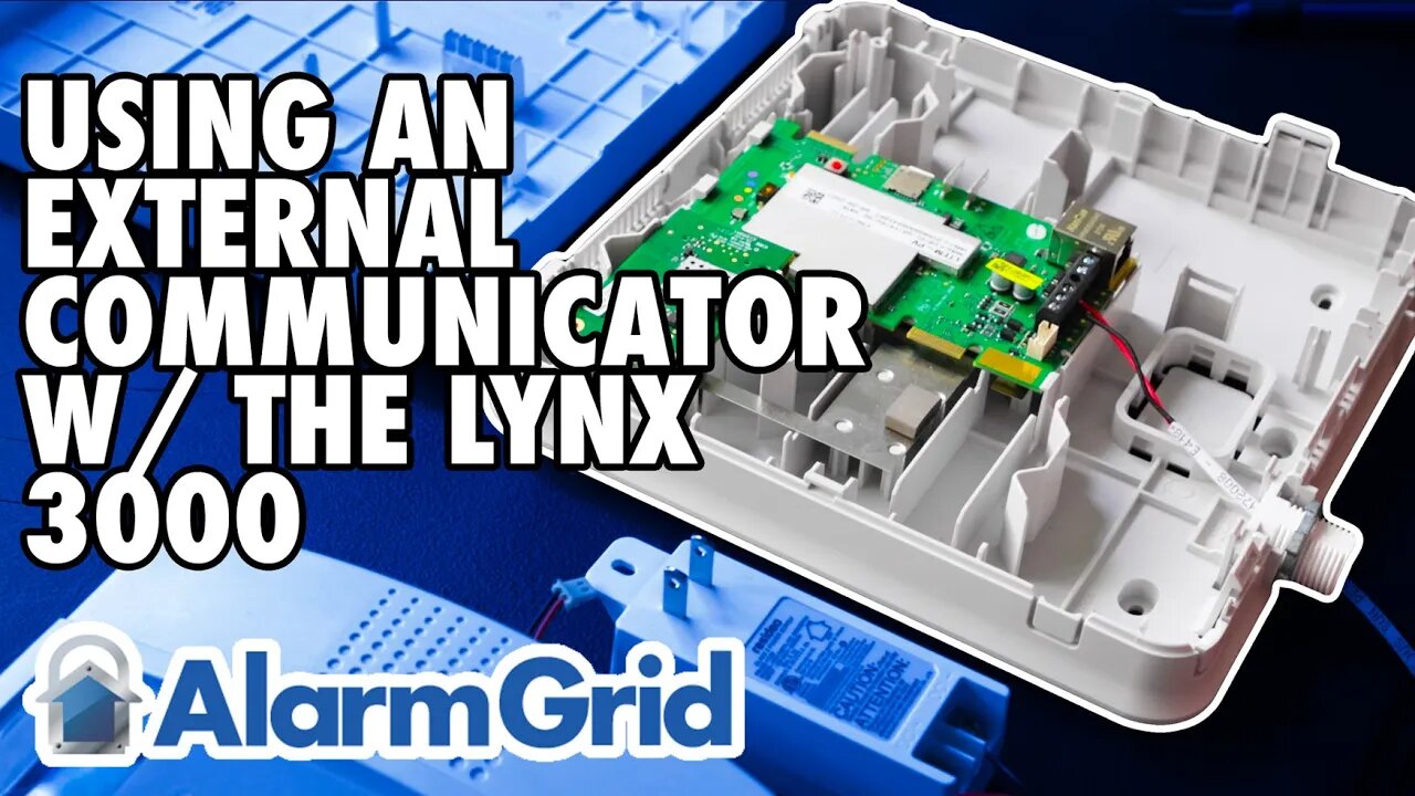
In this video, Darrell from Alarm Grid shows you how to connect an external communicator to a LynxPlus or L3000 panel from Honeywell. There are communicators that are made to work with the L3000 that can be installed inside the panel plastic and are hidden from view. However, those communicators are no longer available, so if you have an L3000 and you wish to upgrade it to an LTE communicator, this is how you do it.
IMPORTANT NOTE: The L3000 can support Total Connect 2.0, however, the LTEM-PA and LTEM-PV communicators will not support TC2 with the L3000 panel. So, if you plan to use Total Connect 2.0, you'll want to choose a communicator other than the LTEM-P Series. The connections will be similar, regardless of which external communicator is used.
Before you begin, be sure that both the L3000 and the communicator are powered down. This will involve unplugging their respective plug-in power supplies, and backup batteries. Once you're sure both pieces of equipment are powered down, continue.
In order to make the proper connections, you will need an LYNXGSMEXTCB wiring harness. These are no longer available from the manufacturer, but you may be able to find one on eBay or a similar market. The LYNXGSMEXTCB plugs into a modular port on the L3000 main board. Depending on the version of the panel, the port is either located at the upper right side (when the panel is opened) of the board, near the hinges that connect the front of the panel to the back. Or it is located on the right side of the board as shown in this video. The cable has a keyed header, so it will only plug in using the correct orientation.
Once the cable has been connected to the panel, route the wires through the wiring access in the back. Now turn your attention to the communicator. Open the communicator and route the wires from the LYNXGSMEXTCB to the communicator through any available wiring access. In this video, we use the wiring port at the bottom of the LTEM-P Series communicator, but different communicators will have different wiring access channels. Just be sure to route the wire so that both the panel and the communicator covers can be closed properly to prevent any tamper warnings.
Because the communicator will need to use its own transformer, only three (3) wires from the L3000 panel will connect to the communicator. These are the Data In, Data Out, and Ground wires. Due to a quirk in the way the L3000 and the LYNXGSMEXTCB are made, the Black wire is actually DC Positive (+) and the Red wire is actually DC Negative (-). This means that you will not use the Black wire from the harness.
On the LTEM-P Series communicator, connect the Green wire from the L3000 to the terminal marked RX. Connect the Yellow wire to the terminal marked TX, and connect the Red wire to the terminal marked GND. If you are using a different communicator just remember that the Green wire will go to ECP Data In on the communicator, and the Yellow wire will go to ECP Data Out with the Red wire from the harness on the L3000 going to the communicator GND terminal. For full instructions, see the FAQ: https://www.alarmgrid.com/faq/how-do-i-use-an-external-communicator-with-a-lynx-l3000.
Once the wiring is completed, you can power up each device based on the instructions for that device. Connect the communicator's battery, then plug in its DC power adapter. Connect the battery to the L3000, then plug in its transformer. To register the communicator, contact your alarm dealer.
https://www.alarmgrid.com/faq/how-do-i-use-an-external-communicator-with-a-lynx-l3000
-
 6:05
6:05
Alarm Grid Home Security DIY Videos
1 year agoPROA7 or PROA7PLUS: Using Lyric Sensors
15 -
 LIVE
LIVE
Slightly Offensive
1 hour agoALMOST SERIOUS: How Mass Legal Immigration DESTROYED Australia | Guest: Maria Zeee
652 watching -
 54:43
54:43
LFA TV
1 day agoTrump vs. Karl-Theodor zu Guttenberg | TRUMPET DAILY 2.18.25 7PM
11.5K3 -
 2:02:21
Revenge of the Cis
6 hours agoEpisode 1449: Boo This
55.7K9 -
 1:20:31
Awaken With JP
7 hours agoWiping Hard Drives, Hire a Criminal Defense Lawyer - LIES Ep 79
95.5K58 -
 1:02:23
In The Litter Box w/ Jewels & Catturd
23 hours agoDEI Kills | In the Litter Box w/ Jewels & Catturd – Ep. 744 – 2/18/2025
126K57 -
 1:06:37
Game On!
5 hours ago $1.02 earnedBreaking Down COLLEGE BASKETBALL BETTING LINES Like a Pro!
44.5K3 -
 1:01:29
John Crump Live
8 hours ago $3.37 earnedMexico Backs Cartels By Threatening To Designate Gun Manufactures As Terrorist!
39.4K12 -
![[Ep 611] DOGE On The March! | Guest Sam Anthony - [your]NEWS | Seditious Dems | Ukraine](https://1a-1791.com/video/fwe1/97/s8/1/q/C/C/3/qCC3x.0kob-small-Ep-611-DOGE-On-The-March-Gu.jpg) 2:14:09
2:14:09
The Nunn Report - w/ Dan Nunn
5 hours ago[Ep 611] DOGE On The March! | Guest Sam Anthony - [your]NEWS | Seditious Dems | Ukraine
44.6K13 -
 1:00:56
The Tom Renz Show
11 hours agoThe War On DOGE Is ALSO A War On The Economy
54.1K13