Premium Only Content

Soldering Wires On Charge Accelerator Stator Half
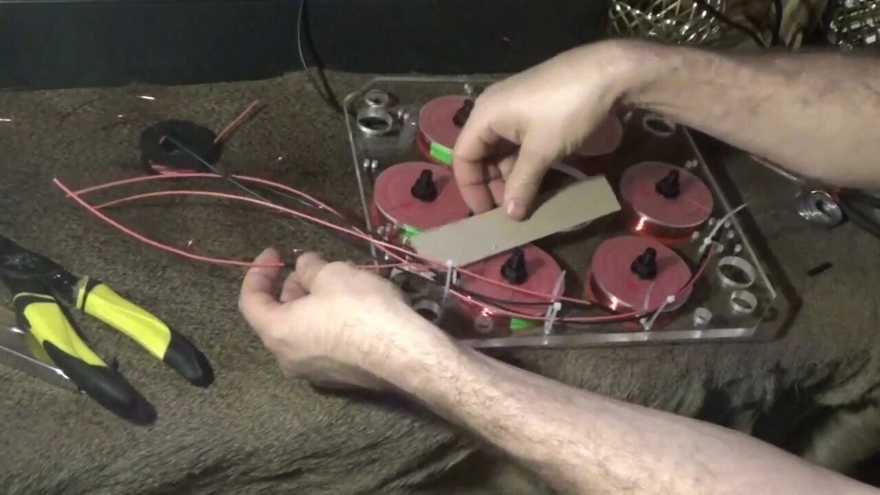
I have finished soldering the wires onto one half of the Q3 charge accelerator stator assembly. Read the full article here: http://www.thedoityourselfworld.com/articles/article.php?id=11401
I used two different colors, red and black, for the assembly of the stator half. This will help me to better identify the coil start and end wires easier when connecting them to the bridge rectifier sets later on.
I ran the coil wires through the small holes in the stator frame so that all the wiring will be on the back side of the coils and away from the spinning magnets.
I used plastic zip ties to hold all the wires neatly in place and out of the way.
The red wire was for the outside wire, or end wire, of the coil. The black wire was for the inside wire, or start wire, of the coil.
When wiring these coils up to the power supply and the output bridge rectifiers it will be important to keep the same orientation of all the coils.
I left about six inches of wire extending past the stator assembly so that I can work with it easier later on.
I routed all the wires neatly around the coils and zip tied them into place. Then I cut the zip ties close so that everything looks nice.
Thanks for watching. Please Subscribe & follow my daily videos.
Troy
http://www.thedoityourselfworld.com
http://www.theoffgridproject.com
Note: Copying this video, in part or in full, is a violation of copyright unless the user has express permission from the owner. Violation of this copyright will be pursued to the fullest extent of the law.
-
 0:32
0:32
The Do It Yourself World
7 years agoExercise Birthing Ball FAIL
81 -
 LIVE
LIVE
Eternal_Spartan
4 hours agoLive at 11am Central!! | Clari Obscur Expedition 33 - Possibly the Best Game of My Life?!?
135 watching -
 13:05
13:05
Cowboy Kent Rollins
1 day ago $7.87 earnedHomemade Cowboy Corn Dogs | Easy Corndog Recipe
31.9K20 -
 LIVE
LIVE
GritsGG
3 hours ago#1 Warzone Win Grind! 🔥
69 watching -
 8:24
8:24
Talk Nerdy Sports - The Ultimate Sports Betting Podcast
3 hours ago4/26/25 - Saturday Annihilation: Vasil’s 8 Sharp Picks and 2 PrizePicks Built for Blood 💥📈
35.1K1 -
 LIVE
LIVE
GamingWithHemp
3 hours agoElder Scrolls Oblivion Remastered Episode #2 Ultra high settings
69 watching -
 2:11:49
Rotella Games
21 hours agoSaturday Morning Family Friendly Fortnite
12.9K5 -
 2:13:45
I_Came_With_Fire_Podcast
12 hours agoRESTRUCTURING THE WORLD- CIVICS CLASS WITH DAN HOLLAWAY
25.4K5 -
 DVR
DVR
Bannons War Room
2 months agoWarRoom Live
14.2M3.58K -
 LIVE
LIVE
Total Horse Channel
1 day agoYELLOWSTONE SLIDE I | SATURDAY
218 watching