Johnson Outboard Lower Unit Crack Repair/Rebuild #7
Video #7 of the Johnson GT 150 lower unit crack repair/rebuild is on starting reassembly
After you have verified that all of the bearings, shafts, and gears are in good shape, and replaced any that are not, you are ready to clean all surfaces of any grinding medium, aluminum fragments, and dirt prior to re-assembly. At a minimum you need to buy the complete lower unit seal kit and replace all seals, O-rings, and gaskets contained in the kit.
During assembly use some sort of lower unit lubricant in my case I am using Amsoil Synthetic Marine Gear Lube SAE 75W/80W-90.
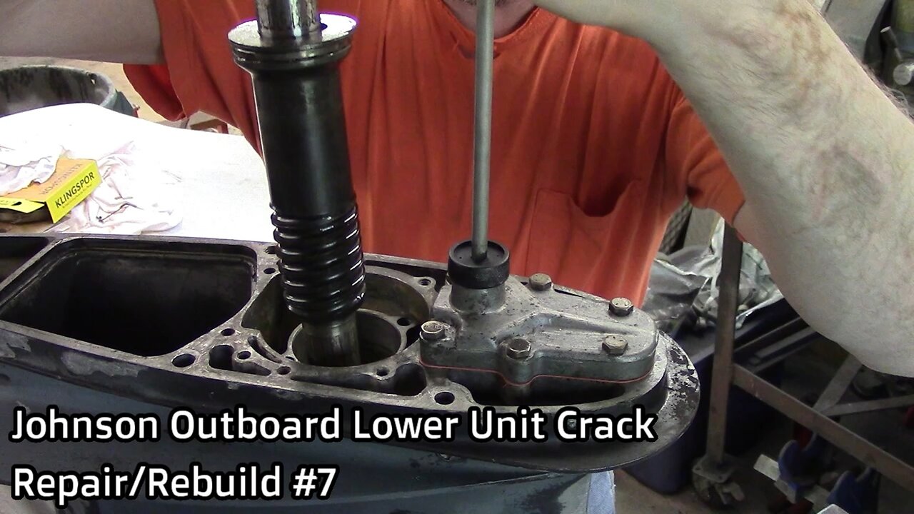
Insert propeller shaft #37 assembly into the lower unit housing, with the shift detent #29 facing the top of the lower unit.
If I were installing it straight & square, it would be much easier!
Ahh there I got it.
Install the new seal/ O-rings on #66 shift rod cover; install the shift rod assembly into the housing, threading the shift rod clockwise into #29 shift detent approximately 7 turns, not tight.
Install the six 7/16” head ¼” bolts securing #66 shift rod cover to the lower unit housing. Use a criss/cross pattern while tightening.
Lubricate and prep the driveshaft #21/24 for installation.
Apply a Loctite 248 to the threads prior to installation of the pinion nut #28.
I struggled installing the pinion gear #26 and pinion nut #28, a much better way is to position the lower unit horizontally and use a magnet tool to install the parts, see a link to a great detailed video in this videos description.
Install the driveshaft #21/24 through the top of the lower unit and the pinion gear #26 and pinion nut #28 through the back of the lower unit. You will have to feel where the shaft is as you raise/lower it slightly to align the splines, and teeth on the gear and shaft, and the same for starting the pinion nut.
I used a big needle nose to install the pinion nut #28, positioning it square and in the center of the shaft is a little tricky.
Nobody ever said this was going to be easy, just take your time and be patient and you’ll get it!
When the nut is correctly positioned, install the driveshaft adapter to the top of the driveshaft #21/24, spinning the driveshaft clockwise and holding the pinion nut #28, 7/8” to get the pinion nut started. If you buy the correct tools for this job it is much easier, I speak of the driveshaft adapter for the top and the pinion nut adapter for holding the nut.
The pinion nut is now installed, torque it to 70 Ftlbs. If you plan to use a open end wrench like I did you will need to grind it down to the thickness of the nut.
Lubricate the driveshaft for installation of #16 the driveshaft upper bearing housing and seal.
Install and tighten the four 7/16” head, 5/16” bolts, again using a criss/cross pattern.
Please come back for video #8 when we will finish assembly.
Very thorough video to watch: https://www.youtube.com/watch?v=_2OV7sL8Zgg
Great information including videos and exploded views of many different OMC models: http://www.sterndrive.info/outboardmotor/index.html
https://www.youtube.com/@HRIservicesllcSturgeonBay
https://www.instagram.com/hri_services/
https://www.facebook.com/HRIServicesllc/
https://www.millerwelds.com/
-
 0:50
0:50
Sean Unpaved
15 hours ago $9.18 earnedWelcome “Unpaved w/ Sean Salisbury” to Rumble
59.4K14 -
 2:10:09
FreshandFit
9 hours agoKicking Out Old Annoying Hoes In Las Vegas!
87.8K117 -
 25:53
25:53
Stephen Gardner
12 hours ago🔥BREAKING: Trump HATING LAWYER busted in $17 million money laundering scheme!
56K143 -
 20:10
20:10
CartierFamily
18 hours agoAndrew Schulz DESTROYS Charlamagne’s WOKE Meltdown on DOGE & Elon Musk!
135K104 -
 33:56
33:56
The Why Files
9 days agoLegend of the 13 Crystal Skulls | From Mars to the Maya
94.1K44 -
 2:56:14
TimcastIRL
12 hours agoEPSTEIN Files DROP, FBI GOES ROGUE, AG Says They COVERED UP Epstein Case w/Amber Duke | Timcast IRL
221K145 -
 1:39:23
Kim Iversen
12 hours ago"Canada's Trump" Is Trudeau’s Worst Nightmare: Is Maxime Bernier the Future of Canada?
103K99 -
 DVR
DVR
Bannons War Room
10 days agoWarRoom Live
2.69M447 -
 16:06
16:06
The Rubin Report
19 hours agoProof the Islamist Threat in England Can No Longer Be Ignored | Winston Marshall
113K121 -
 2:07:07
Robert Gouveia
16 hours agoFBI Files Coverup! Bondi FURIOUS; SCOTUS Stops Judge; Special Counsel; FBI Does
140K101