Premium Only Content

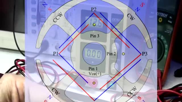
Asymmetric brushless Part 1
I had problems with one of the sensors...one of its outputs (blue)started to show a small resistance value (20 ohms) with positive Vcc, not good, that pair was pulsing too weak, had to replace IC... I also had problems with small original caps retaining some Milli Voltage steadily, and not discharging to zero or close to like supposed to...due to higher radiant, higher BEMF Spikes because of more copper on same steel volume...I will eventually measure this exact running values when I connect all four outputs to Scope...The Solution was higher Voltage rated caps, same value, or 2.2 uF but 100V...then retention of voltage went to 0.04 to 0.02...or nothing...we have more voltage in our fingers...
In future tests...I am looking at adding some small Non Polarized Caps Parallel to each Pair, about same timing capacitance or 2.2 uF...creating "Momentary" LC Tank circuits for each...in order to "flash" store Radiant in each Off Time Pulse, reversing magnetic polarity...and use it more robust to assist motor Pairs while being turned On by Hot Pulses...same deal we had before on our Brush Type Asymmetric Machines, except that here we have plenty of space to do it externally and stationary...
The Basic Results were:
Two Symmetric Fans in Parallel running at :
11.5 Volts drew 0.47 Amps, each outputting around 2000 RPM's
One Asymmetric Fan, connecting All Pairs:
11.5 Volts drew 0.39 Amps, outputting around 2700 RPM's
At 13.8 Volts drew 0.46 Amps reaching around 3000 RPM's
The idea of building this type of small Four Poles ...is to be able to "modulate" sections like this structure and spread them along bigger circumference machines...in series, to add resistance values, decreasing amp draw...every 90º, 120º...etc,etc. I am currently working on a bigger 24 Teeth Laminated Core for future Asymmetric BLDC model...maybe a Six Phase Circuit...a P24, 48 Coil Spiral...
-
 LIVE
LIVE
Alex Zedra
3 hours agoLIVE! Playing Verdansk all night
687 watching -
 1:38:36
Glenn Greenwald
6 hours agoProf. John Mearsheimer on Israel's Destruction of Gaza, Trump Admin Attacks on Universities & Speech, Yemen Bombings, Tariffs & Competition with China; Plus: Q&A with Glenn | SYSTEM UPDATE #434
112K62 -
 LIVE
LIVE
SpartakusLIVE
1 day agoThe MACHINE is back after a RESTFUL 4 hours of sleep
732 watching -
 LIVE
LIVE
I_Came_With_Fire_Podcast
11 hours agoTARIFF TAKEOVER | REDCOATS 2.0 | DOGE FINDS SOMETHING HORRIBLE
278 watching -
 LIVE
LIVE
Eternal_Spartan
3 hours agoLive at 9pm Central! Come Hang Out w/ a USMC Vet Playing HALO! Can't Wait to See Everyone!!
159 watching -
 LIVE
LIVE
EzekielMaxwellVT
6 hours agoVTuber/VRumbler - Vampire The Masquerade - Listening to the voices in Jo's head
55 watching -
 LIVE
LIVE
Welsh Girl
5 hours ago🔴 Minecraft Basics Explained – DAY 1
70 watching -
 LIVE
LIVE
SynthTrax & DJ Cheezus Livestreams
1 day agoFriday Night Synthwave 80s 90s Electronica and more DJ MIX Livestream Trip-Hop SPECIAL EDITION
436 watching -
 4:03:27
FusedAegisTV
9 hours agoRumble Smackdown! #001 Street Fighter 6 $500 Online Tournament
50.8K6 -
 55:58
55:58
BonginoReport
6 hours agoCan Trump Make TikTok Great Again? (Ep. 20) - Nightly Scroll with Hayley Caronia - 04/04/25
130K79