Premium Only Content

Asymmetrical conversion of the prime mover
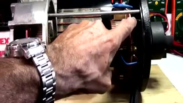
We provide Source to Input, energized Pair of Coils build a "per-conceived" magnetic field that would be immediately attracted repulsed away from original positioning, Coil will disconnect from source, and will travel free...separated from original brush contact...here, in this nano seconds...it will build an opposed magnetic field, therefore an opposed voltage potential (just like the Inductor does at the Booster-SEPIC-Buck Converters, that is why I spent hours building the 3D Graphics of the Inductor part at my video...lol)...Inductors, as my Coil in my first Thread...build an opposed magnetic field provided by Radiant....The "Princess"... . I have much better proof of that fact, coming soon...well not too soon...but coming. When Coil reverses magnetic polarity, it happens exactly at a point where it will assist rotation...(And here you guys could understand Joe Newman statements, as well as many Free Energy Inventors...that their motors used the C EMF to "assist rotation" which did not make sense to anyone..but I did understand what they meant... You have to realize that Symmetry creates the Counter Effect, by providing an inverse Input to Source...that is NOT the normal reversing that occurs when Coil is interrupted... or Inductor in a booster circuit board...Symmetry KILLS the Natural Counter Effect, by creating a fake one with Hot electricity...The Natural Radiant Counter Effect will never get out ever...unless we FREE those Coils at least a small portion of the time... Resuming, We are using the Commutator Switching, just as an Electronic Oscillator Switcher, but mechanically operated...So, Charged Inversely Inductor will travel to "Delivery Brushes"(Output) where We collect it... You Guys need to get "Familiar" with The way SEPIC Converters work...I could not do it on video because of time... But a SEPIC is a Dual Inductor Converter...it performs a Charge-Discharge Alternatively of both Inductors...through a Non Polarized Cap between the two Inductor legs connected to output...I have done exactly same connections with my motors...except the Inductors are also performing a Mechanical Rotation (using their swapping magnetic fields) A CUK Converter is more complicated function and it "inverts the output",so it is NOT a good example for this understanding... And Yes, We do "Add" and not subtract the Input to Output Values...they are not opposed anymore, but on our side...therefore: Ea (Input) and (-Ec) (Counter?)..NO MORE, it should be written as Ef (E forward), and have a + sign in front...then it will be: Ea+Ef=Ev (Effective Armature Voltage)...disregarding R to One Ohm (1.0) I hope this explanation made it a bit clear...hope so...
-
 58:44
58:44
Flyover Conservatives
23 hours agoInauguration Danger: Is Trump Walking Into a Trap? - Sheriff Richard Mack | FOC Show
28.7K12 -
 1:48:50
Precision Rifle Network
1 day agoS4E1 - Guns & Grub - Back like a bad rash!
37.7K3 -
 1:11:22
Common Threads
7 hours ago $3.49 earnedLIVE DEBATE: Trump Pushes U.S. Expansion, Cali Fires Spark Political Outrage
53K6 -
 54:46
54:46
LFA TV
11 hours agoThe LA Apocalypse | TRUMPET DAILY 1.9.25 7pm
45.7K20 -
 57:50
57:50
theDaily302
16 hours agoThe Daily 302-CORY GAUTEREAUX
50.2K -
 9:49
9:49
Tundra Tactical
6 hours ago $2.11 earnedISIS ATTACK Screams Incompetence.
41K3 -
 47:51
47:51
Anthony Pompliano
1 day ago $8.50 earnedRegulators Tried To End Bitcoin?!
73.3K7 -
 8:39:59
BSparksGaming
11 hours agoMarvel Rivals Season 1 is ALMOST HERE! Time to Grind!
61.4K2 -
 45:26
45:26
Kimberly Guilfoyle
9 hours agoBreaking News Coverage of LA Fires, Live with Asm Bill Essayli & Jennifer Kelly | Ep. 187
62.8K74 -
 1:36:05
Redacted News
9 hours agoBREAKING! Trump Slams Communist California Dems over Wildfire Disaster | Redacted News
138K321